
This caused an AC voltage in one half of the rotor which was rectified by rotating diodes and fed to other half of rotor which in turn caused an output from the output stator. These used an AVR to supply current to a static field. However the larger sets used a completely different method. The output coils rotated with static field and four slip rings.
#1960 lister diesel generator full#
Then the parallel winding resistor was set to give 240 volt then we put on a load quite high often full load and the series resistor was set to 240 volt.Īs load increased the voltage would vary but would be some where between the 220 and 240 range it was a little hit and miss.
#1960 lister diesel generator generator#
The generator was first set to 1500 RPM I used a frequency meter and set to 50 Hz but rev counter would do the same. One set in series the other in parallel the series set had a huge rectifier and parallel a small one and both also had resistors to set the output. Seem to remember out lighting towers used a Conveyors generator which had two sets of field windings. My method of repair back in 1980 was to swap parts good one to one which was not running until fault swapped then order up that part. Some used a large capacitor but I never worked out exactly how. Often disabled by farm managers as there was a tendency not to check oil before starting.

There was one used a lot on the Falklands where the generator was also a started motor and switching on the lights auto started the generator. Frequency is still engine speed dependent, but the output voltage is controlled by the size of the capacitor.The Lister engine was used to drive many generators with many methods used to control them. (Unless you have a brushless design, then there will be a large capacitor connected to 1/2 the output of the stator, an extra winding on the rotor and a rectifier between the two sets of windings on the rotor. The throttle (governor) is adjusted to get the correct frequency. By varying the voltage in the rotor, the AC output voltage can be adjusted. There may be an adjustable voltage regulator associated with the rectifier. By spinning the stable magnetic field within the stator, AC is induced at the frequency the rotor is spun at. If you disassemble your existing genset, you will find the output of the stationary windings (the "stator") is connected to a rectifier that sends DC into the rotating armature (the "rotor") via a pair of brushes and slip rings. The engine is located near a small fresh water lake so it has not seen salt use and seems too be in pretty good shape.Įven though an alternator produces AC power, internally it needs DC in the fields to produce the magnetic field. Anyway, has anyone ever done this kind of project? I think it would be worthwhile since these engines get about 20 000 hours between in-frame rebuilds so realistically this should last me the rest of my life as a back-up.

I can likely score it for about 500 USD (the exchange rate is TERRIBLE right now for us in Norway).

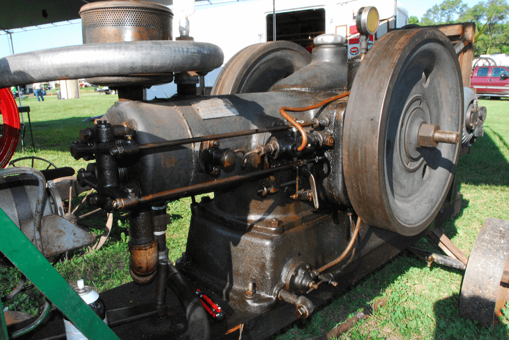
The benefit is that the engine's RPM under normal use is 1500 so I would imagine this engine would have a longer service life than my Yanmar. I would like to make this the powerplant for a larger generator. I have the chance to buy a Lister 18 HP 2 cylinder diesel engine. I currently have a Yanmar diesel generator which is a great machine, however it runs at 3600 RPM, which I think results in a machine that is not a long-term power solution. I have been considering getting a backup power supply for a while.


 0 kommentar(er)
